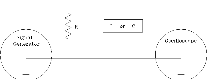
We wish to measure the magnitudes of the impedances ![]() and
and ![]() by measuring
by measuring ![]() and V
and V ![]() which will be proportional to
the impedances if
which will be proportional to
the impedances if ![]() is kept constant.
However, as the frequency of the signal generator is varied,
not only does the impedance of L and C change,
but the impedance of the whole circuit changes.
Hence, if V (the amplitude of the signal generator's output)
is left constant when the frequency is changed,
is kept constant.
However, as the frequency of the signal generator is varied,
not only does the impedance of L and C change,
but the impedance of the whole circuit changes.
Hence, if V (the amplitude of the signal generator's output)
is left constant when the frequency is changed,
![]() will therefore change.
To keep
will therefore change.
To keep ![]() constant, we need to adjust
constant, we need to adjust ![]() so that the voltage across the resistor R remains constant.
so that the voltage across the resistor R remains constant.
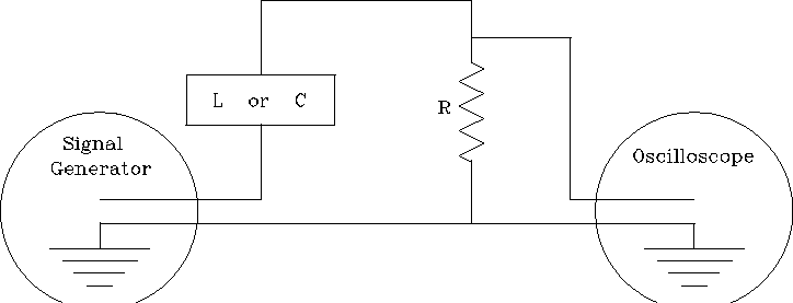
Use the oscilloscope to measure the voltage drop
first across L and then across C
for a wide range of frequencies,
measuring ![]() between each change of frequency
and adjusting
between each change of frequency
and adjusting ![]() to keep
to keep ![]() (and therefore
(and therefore ![]() ) constant.
) constant.
To measure ![]() , the circuit must be reconnected so that
the signal generator and the oscilloscope share a common ground.
, the circuit must be reconnected so that
the signal generator and the oscilloscope share a common ground.
You should check the frequency settings of the signal generator by measuring the periods of oscillation with the oscilloscope.
Plot the results (choosing variables for ordinate and abscissa with
some forethought) so as to make a simple graphical comparison with
the equations for ![]() and
and ![]() . Note that if y=kx, then the
graph of y vs. x should be a straight line. If y=k/x, then the
graph of y vs. 1/x should be a straight line.
What values of L and C are implied by your graphs?
. Note that if y=kx, then the
graph of y vs. x should be a straight line. If y=k/x, then the
graph of y vs. 1/x should be a straight line.
What values of L and C are implied by your graphs?
In practice, the elements may not be pure R, L and C.
The resistor may have some associated inductance,
the inductance may have an appreciable resistance, etc.
Do your curves show any evidence of these effects
(do they show any systematic deviations from the expected behaviour)?
Is there any danger that connecting the oscilloscope
will alter the behaviour of the circuit
(the 'scope has an input resistance of 1 M ![]() ,
with an input capacitance, in parallel, of 35 pF)?
,
with an input capacitance, in parallel, of 35 pF)?