Next: 6.2 Refraction
Up: Geometrical Optics
Previous: Equipment Needed
- Position the incandescent light source
on the left end of the optical bench and place the
angular translator about 25 cm from the end of
the light source housing. Make sure the 0
 mark
lies on a line parallel to the bench.
Adjust the rotating table so that the scored lines
run perpendicular and parallel to the bench.
mark
lies on a line parallel to the bench.
Adjust the rotating table so that the scored lines
run perpendicular and parallel to the bench. - Attach the aperture mask to
the standard component carrier and place it between
the light source and angular translator so the the mask is
d centimeters from the center of the translator. The distance
d (about 6.5 cm) is the measured distance from the center of
the angular translator to the first analyzer holder on the movable arc.
(See Fig. 6.1.2.)
- Center the viewing screen of the special component carrier
designed for use with the angular translator,
and place the assembly on the rotating table
of the translator so that the front surface of
the viewing screen coincides with the scored line on
the table which runs perpendicular to the optical bench.
- Now switch on the light and adjust the aperture mask's position
(don't move the component carrier) until the entire image
is on the viewing screen.
With the aid of the millimeter scale marked on the screen, center the
image horizontally. Turn the screen 90 and center the image
vertically.
- Replace the viewing screen with the flat surface mirror
(be careful not to touch the front surface of the mirror)
such that the mirror surface coincides with
the perpendicularly scored line.
Move the viewing screen to the
first analyzer holder on the movable arc.
- Rotate the table a set number of degrees (for example 30 ),
and then move the arm until the reflected image is centered horizontally
on the viewing screen. Record the angle which the arm makes with the mirror.
Repeat for several settings of the rotating table. What is the relation
between the angle of incidence and the angle of reflection? Both of these
angles are measured from the ray to the normal of the reflecting surface.
- Rotate the viewing screen and measure the vertical position of the
reflected image. Compare this with the vertical position of the
incident beam (from your initial alignment of the laser beam).
Check that the incident ray, reflected ray and normal to the mirror
at the point of reflection all lie in the same plane.
- Replace the flat mirror with the glass plate, taking care that the front
surface coincides with the scored line.
- Rotate the table until the glass plate rests at a convenient angle with
the optical bench.
- Move the arm until the reflected image is visible
on the viewing screen. How many images of the beam are there? Why?
- The brightest image is the reflection from the front surface
of the glass. Center this image on the screen and record the angle
which the translator arm makes with the glass plate.
Repeat the procedure with the rotating table set at
several different angles. What is the relation between the angle
of incidence and the angle of reflection?
- Measure the height of the middle of the reflected image;
determine whether the incident ray, reflected ray and
normal to the glass at the point of reflection are coplanar.
- Replace the glass plate with the acrylic plate
and repeat the above procedure.
Does the material used as the reflecting surface affect
the relationship between the angles of incidence and reflection?
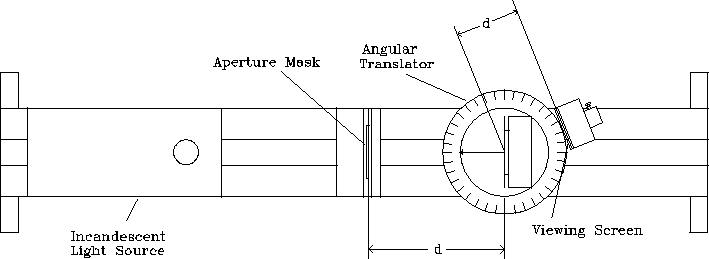
Figure 6.1.2: Experimental Setup.
Next: 6.2 Refraction
Up: Geometrical Optics
Previous: Equipment Needed