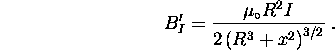
The magnetic field produced at the position of the electron beam by a current I flowing through the coils must be computed. For a single turn of wire of radius R, the field on the axis at a distance x from the plane of the loop is given by:
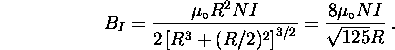
For the arrangement in Figure 2, there are two loops with N turns each, separated by a distance equal to the coil radius R. The coils contribute equally to the field at the center:
The above equation is true only as long as the thickness b of the coil is negligible compared to R.

Figure 2: Helmholtz coils used to produce a uniform magnetic field.
This arrangement is known as a pair of Helmholtz coils and has the advantage that the field is uniform in the region near the center.
The coils used have 72 turns of No. 14 copper wire on each loop and a mean radius R of 33 cm. The resulting field is then
![]()
The net field B in which the electrons move is not ![]() alone,
but the resultant of the earth's field
alone,
but the resultant of the earth's field ![]() and
and ![]() .
If the equipment is oriented so that the field of the Helmholtz coils is
parallel to that of the earth, and if the current through the coils
causes
.
If the equipment is oriented so that the field of the Helmholtz coils is
parallel to that of the earth, and if the current through the coils
causes ![]() to be directed opposite to
to be directed opposite to ![]() , then
, then
![]()