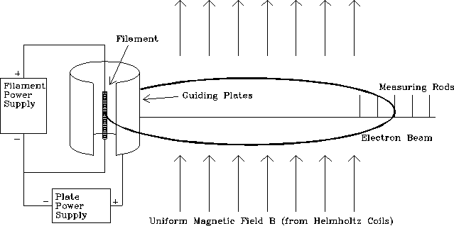
Figure 1: Diagram of the interior of the sealed glass tube.

Figure 1: Diagram of the interior of the sealed glass tube.
Figure 1 shows the filament surrounded by a small cylindrical plate. The filament is heated by passing a current directly through it. A variable positive potential difference of up to 100 volts is applied between the plate and the filament in order to accelerate the electrons emitted from the filament. Some of the accelerated electrons come out as a narrow beam through a slit in the side of the cylinder. The entire tube is located inside a set of coils, which produce a uniform magnetic field B perpendicular to the electron beam. The magnitude of the field can be adjusted until the resultant circular path of the electron beam just reaches one of the measuring rods. These rods are located along a cross bar, which extends from the cylinder in a direction perpendicular to that in which the electron beam was emitted -- i.e. along a diameter of the circular orbits.