


Next: 2.2.1 Time-Differential
Up: 2 Muon Spin Rotation
Previous: 2.1 Muons and Muon
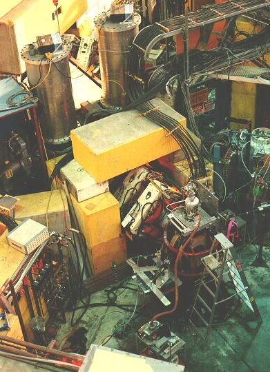
An experimental area used for  is shown in
Fig. 2.3, this one being
the M20 channel at the TRIUMF laboratory.
The experimental apparatus is positioned at the
end of the secondary beamline, downstream from the final
focusing quadrupole magnets.
is shown in
Fig. 2.3, this one being
the M20 channel at the TRIUMF laboratory.
The experimental apparatus is positioned at the
end of the secondary beamline, downstream from the final
focusing quadrupole magnets.
Figure 2.3:
A view of the M20 secondary channel and experimental area
of the TRIUMF
laboratory, configured with a conventional
spectrometer capable of transverse and longitudinal
field measurements. (G.D.Morris)
 |
The spectrometer consists of a set of Helmholtz magnet coils
to produce a externally applied
magnetic field, a cryostat (or for some experiments an oven)
for controlling sample temperature, and a set of fast
scintillation detectors that signal the passage
of incoming muons and outgoing positrons.
Most beamlines used for
incorporate spin rotators into
the positron separators that allow one to
precess the muons spins in flight by  with respect
to their momenta before they arrive at the experiment.
This spin-rotated mode allows the experimenter more flexibility in
orienting the initial spin polarization
with respect to the applied field.
This is especially useful when the experiment to be performed
requires a strong magnetic field transverse to the muon spin, which would
otherwise steer the beam off the sample.
with respect
to their momenta before they arrive at the experiment.
This spin-rotated mode allows the experimenter more flexibility in
orienting the initial spin polarization
with respect to the applied field.
This is especially useful when the experiment to be performed
requires a strong magnetic field transverse to the muon spin, which would
otherwise steer the beam off the sample.
Next: 2.2.1 Time-Differential
Up: 2 Muon Spin Rotation
Previous: 2.1 Muons and Muon